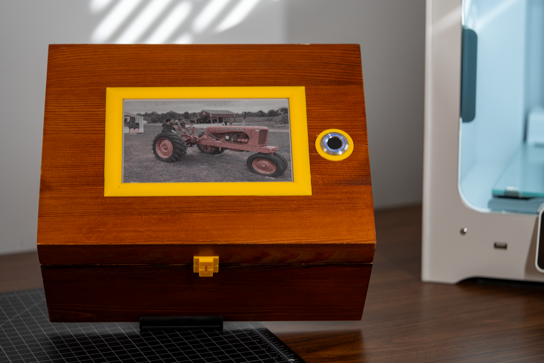
Last September I decided to build my son a custom keepsake box for his birthday. Then, I realized I knew nothing about woodworking, so I pivoted into building him a custom "memory box" that has an e-paper display, a fingerprint scanner, and a whole Linux operating system under the hood.
In this post, I'll talk about the technical details of the project. I also made a YouTube video about it.
The Idea
I wanted to build my son something that can store memories and be an heirloom he uses throughout his life. After some brainstorming and lots of terrible ideas, I landed on putting an e-paper display on top of a wooden box that will rotate between photos throughout the day.
I also decided to add a fingerprint scanner to the top of the box because, ever since my son saw me use a fingerprint scanner at his daycare, he's been dying to try one.
Here's a render I made in Blender to illustrate what the plan was:
The Prototype
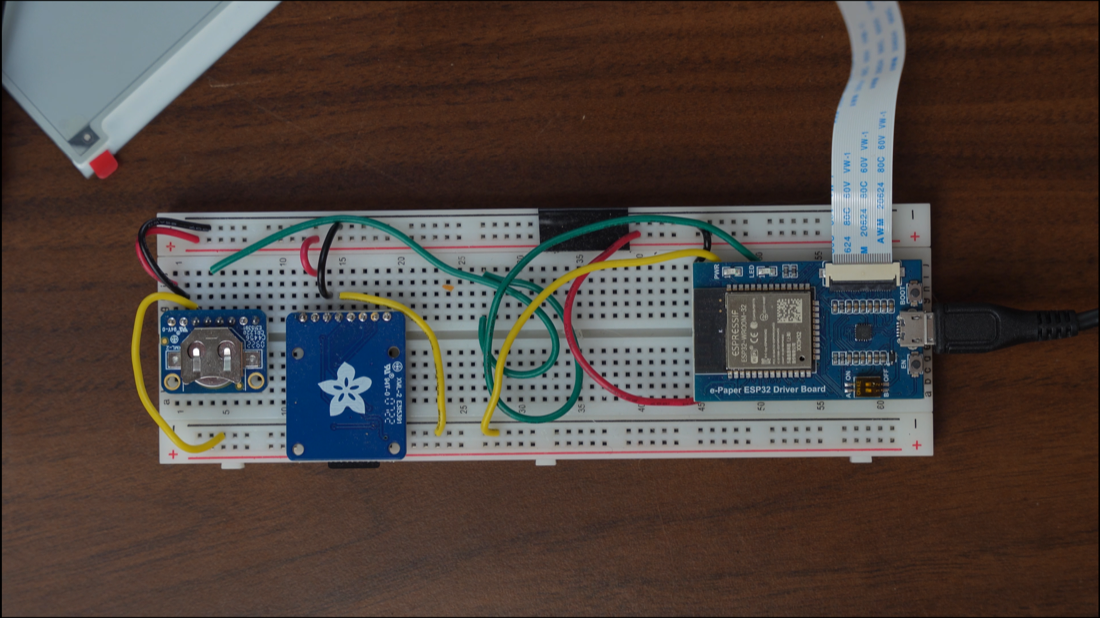
I originally hoped to build this with an ESP-32 microcontroller and even created a prototype using the Waveshare ESP-32 Driver Board. But, after hooking up an SD card reader, real-time clock (RTC), and fingerprint scanner, I realized it wasn't the best fit. This is because: when someone scans their fingerprint, I want the box to find a photo with them in it. But, implementing a "tagging" system with a microcontroller would be fairly complex and time-consuming compared to a single-board computer.
I switched the prototype to a Raspberry Pi Zero W running Raspberry Pi OS and installed PostgreSQL to store the memories. Now, when someone scans their fingerprint, the box will query the database for photos tagged with that person's identifier.
Switching to the Raspberry Pi also lets me SSH into the box, increasing my ability to add features and debug problems.
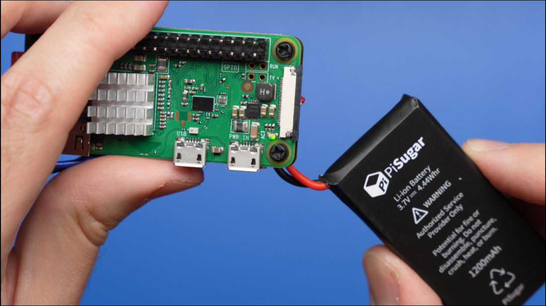
I wanted the box to be somewhat portable so I added a battery using a battery management module called a PiSugar 3. This gave the box a ton of functionality, like:
- The box can shut itself down when its battery is getting low so the SSD and SD card don't get corrupted.
- The box can stop updating the display if it thinks it's about to shut down from a low battery soon.
I added a Python script to the Raspberry Pi that listens for new memories over WiFi. When it receives a memory - which includes a photo, a description, a list of people tagged in the photo, and other metadata - it saves everything to the SSD and PostgreSQL database. I have this Python script running as a Linux service so it runs whenever the box reboots.
The Python script listens for a multi-part form upload that looks something like this:
POST /media-direct-upload HTTP/1.1
Content-Type: multipart/form-data; charset=utf-8; boundary=__X_PAW_BOUNDARY__
Host: 192.168.1.8:2358
Connection: close
User-Agent: Paw/3.3.1 (Macintosh; OS X/14.1.1) GCDHTTPRequest
Content-Length: 413

--__X_PAW_BOUNDARY__
Content-Disposition: form-data; name="metadata"

{
  "update_display_immediately": true,
  "media": {
    "date": "2023-10-30",
    "description": "Teddy at Halloween",
    "people": [
      "Mike Buss",
      "Theodore Buss"
    ]
  }
}
--__X_PAW_BOUNDARY__
Content-Disposition: form-data; name="file"
Content-Type: application/octet-stream
ALL_THE_PHOTO_CONTENT_HERE!
--__X_PAW_BOUNDARY__--
Wiring
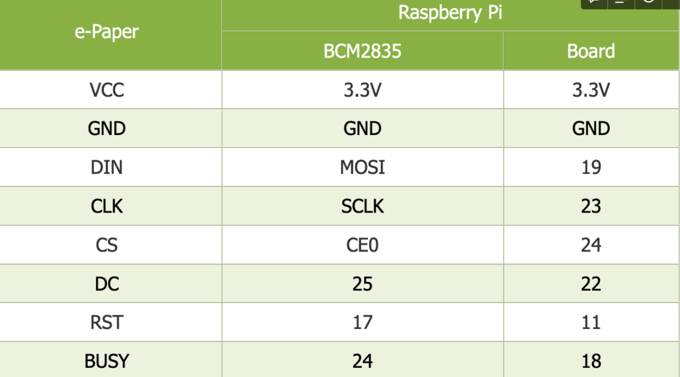
I connected the Raspberry Pi to the E-Paper display using a Waveshare e-Paper Driver HAT, The connections are:
I connected the Raspberry Pi to the fingerprint scanner with these instructions, courtesy of Adafruit:
- Pi GND to sensor GND
- Pi TX to sensor RX
- Pi RX to sensor TX
- Pi 3.3v to sensor VCC
The colors for my fingerprint sensor wires didn't match the colors in the Adafruit instructions so I had to use the manual to figure which wire corresponded to which function.
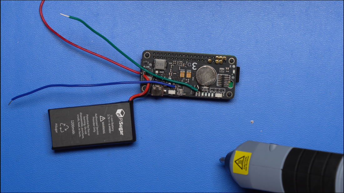
Then, I connected the SSD to the Raspberry Pi with a USB cable. And, I connected the PiSugar 3 battery by screwing the two boards together, which connected the pogo pins from the PiSugar 3 board to the Pi.
I also soldered some wires onto the PiSugar 3 that let me add two buttons to the box: one to power it on and off, and one to trigger a custom script. Right now, the custom script will clear the e-paper display for if I need to store it for a long period of time (something the manual recommends).
A Note on Image Processing
Because I'm using an e-paper display, I needed to process the photos into something the display could understand before updating it. If you'd like to read more on how I did this, Adafruit published an excellent article going over the different methods.
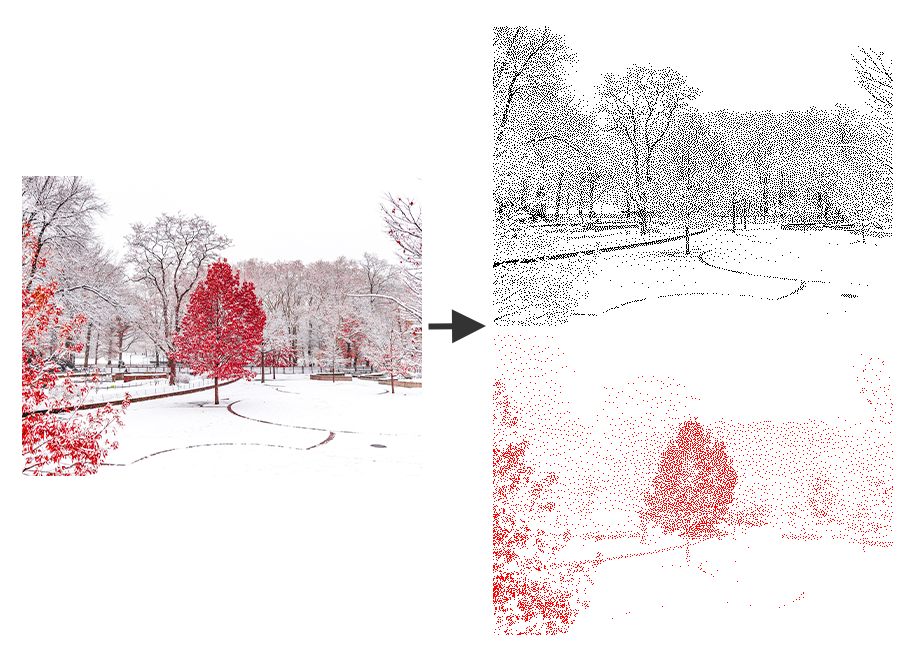
I ended up using the Floyd Steinberg dithering method. If you'd like a simplified explanation of how this works, expand the section below.
Here's a visualization of the input (left) and output (right) for the script I wrote. The top output image represents the black pixels and the bottom image represents the red pixels. Anything white will be white on the display.
After switching to a Raspberry Pi, I moved all of this image-processing logic to the box itself, as opposed to the device uploading the memories. You can find the source code for this below:
import sys
import io
import os
import traceback
from wand.image import Image as WandImage
from wand.color import Color
from PIL import Image

IMAGE_WIDTH = 800
IMAGE_HEIGHT = 480


def process_image(filename, output_folder, custom_filename=None):
    red_image = None
    black_image = None
    try:
        with WandImage(filename=filename) as img:
            img.resize(IMAGE_WIDTH, IMAGE_HEIGHT)

            with WandImage() as palette1:
                with WandImage(width=1, height=1, pseudo="xc:red") as red:
                    palette1.sequence.append(red)
                with WandImage(width=1, height=1, pseudo="xc:black") as black:
                    palette1.sequence.append(black)
                with WandImage(width=1, height=1, pseudo="xc:white") as white:
                    palette1.sequence.append(white)
                palette1.concat()

                img.remap(affinity=palette1, method="floyd_steinberg")

                red = img.clone()
                black = img.clone()

                red.opaque_paint(target="black", fill="white")
                black.opaque_paint(target="red", fill="white")

                red_image = Image.open(io.BytesIO(red.make_blob("bmp")))
                black_image = Image.open(io.BytesIO(black.make_blob("bmp")))

                red_image = red_image.convert("1")
                black_image = black_image.convert("1")

                base_filename = (
                    custom_filename
                    if custom_filename
                    else os.path.splitext(os.path.basename(filename))[0]
                )
                os.makedirs(output_folder, exist_ok=True)
                black_output_path = os.path.join(
                    output_folder, f"{base_filename}-black.bmp"
                )
                red_output_path = os.path.join(
                    output_folder, f"{base_filename}-red.bmp"
                )

                black_image.save(black_output_path)
                red_image.save(red_output_path)

                return black_output_path, red_output_path

    except Exception as ex:
        print(f"traceback.format_exc():\n{traceback.format_exc()}")
        return None


if __name__ == "__main__":
    print("Running...")

    file_path = sys.argv[1] if len(sys.argv) > 1 else "sample.jpeg"
    output_folder = sys.argv[2] if len(sys.argv) > 2 else "output"
    custom_filename = sys.argv[3] if len(sys.argv) > 3 else None

    red_image, black_image = process_image(file_path, output_folder, custom_filename)

    if red_image is None or black_image is None:
        print("Error processing image")
        sys.exit(1)
The Mechanical Pieces
After finishing a working prototype, I moved to the mechanical design. I knew there would be a few challenges here - at least for someone who normally lives in software. For example:
- How would I mount the e-paper display to the top of the lid so it lay flush?
- How would I mount the electronics to the bottom of the lid?
- How do I prevent a three-year-old from destroying this within seconds of receiving it?
Because I know nothing about woodworking, I purchased a wooden keepsake box as a foundation for the project. Then, I modeled it in Fusion 360 so I could start designing the different components.
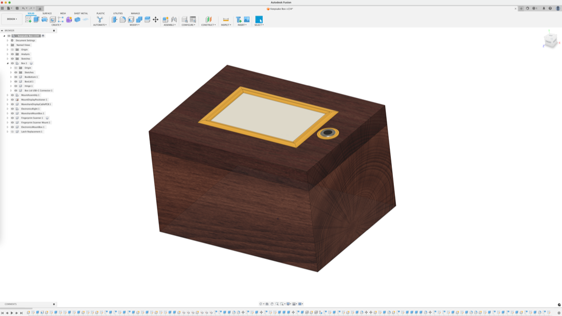
I started by figuring out the mounting mechanism for the e-paper display. First, I cut a section of the lid. Then, I 3D-printed a component for the e-paper display to sit into. This component was designed to mount to the bottom of the lid and place the display perfectly flush with the top of the box. Then, I designed a frame to go around the e-paper display.
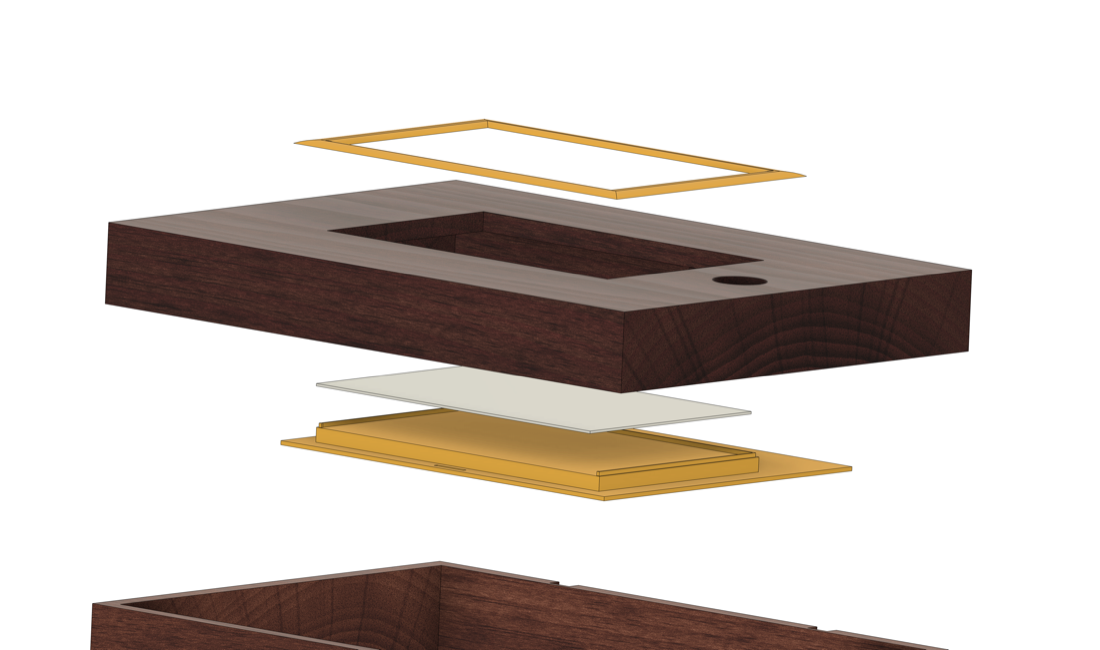
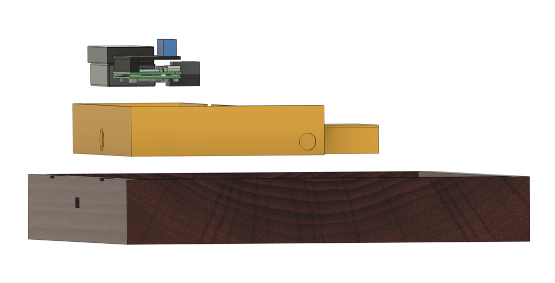
Here is an exploded side view of the lid, showing how the electronics fit into the enclosures:
One of the electronic enclosures has two small circles cut into its lid. This lets me expose two buttons that are recessed into the enclosure, allowing me to reboot the device or clear the display. I can press either of these buttons with a toothpick or small pen. Here is a test print I did to make sure the holes lines up correctly before printing the whole lid:
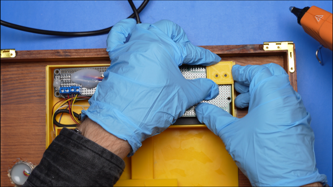
I used some hot glue on the wires to make sure they don't come loose when placing the components in the box, or when the box is being thrown around the room.
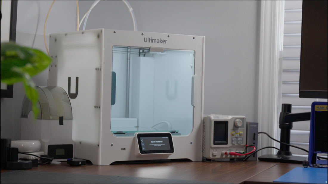
To print these components, I used an Ultimaker S3 with the Ultimaker PLA Filament (in yellow).
The Software
Being a software engineer, this was the only part of the box I was somewhat qualified to build.
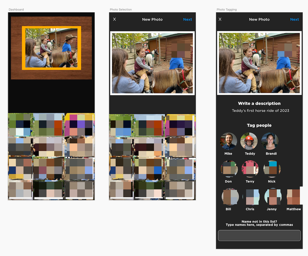
I wrote an iPhone application that can pull photos from the Photos app and upload them directly to the box. My wife and I can add descriptions to each photo and tag people in them. When they're uploaded, they're added to the rotation of random photos the box selects from.
Here's a design I made for the app in Sketch with most of the photos blurred for privacy reasons:
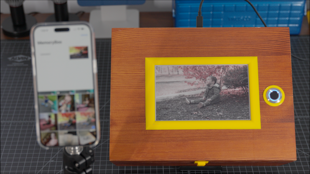
And here's the app running next to the box, updating the current image:
Lessons Learned and Next Steps
I'm happy with how the box turned out, but there are several things I'd like to change down the road:
- I want to be able to manage existing memories from the iPhone app. Right now, if I accidentally upload an incorrect image, I need to use a PostgreSQL tool to remove it.
- I want to re-visit using a microcontroller for this project so I can design a custom (tiny) PCB.
- I want to have automatic backups for the PostgreSQL database and photos so it can survive longer - or at least be reincarnated in the event of a catastrophe!
Also, there were a few key take-aways from this project that I'll carry on to the next project:
-
More than half of the components I ordered from Amazon arrived defective. In the video I created for this project, I discuss this more. I didn't exaggerate for the sake of dramatic effect; the e-paper display, PiSugar 3, and SD card all arrived with various levels of malfunction or defects. (Although, as I said in the video, my dog may have damaged the SD card...)
-
It's important to find a balance between planning and action. In this project, I leaned too heavily towards action, choosing to start with an ESP32 without fully considering its limitations for the "people tagging" system. While I could have made this work, opting for a Raspberry Pi from the outset would have spared me considerable time and effort.
I hope you enjoyed this project. If you have any suggestions for this project, or would like to contact me, please reach out on X or via email.
You can download the code and CAD files here.
I also made a YouTube video on this for fun. If you're interested, you can find it below.
Parts List
Below is a list of parts I used to make the box.
Note these are the only affiliate links in this post. By using these links to purchase any items, you're directly supporting future projects at no additional cost to you. Thank you for your support.
- Wooden Box: Link
- Raspberry Pi Zero W Link
- Red/White/Black E-Paper Display: Link
- E-Paper Driver Board (Prototype): Link
- Real-Time Clock (Prototype): Link
- E-Paper Driver Board (Raspberry Pi): Link
- Fingerprint Scanner: Link
- PiSugar 3 (Battery Circuit + Battery): Link
- Alternative Battery Circuit + Battery: Link
- Portable SSD (250 GB): Link
- Raspberry Pi Prototyping Board: Link
- Raspberry Pi Breadboarding HAT: Link
3D Printing: